
My latest paper is now available here or on Vixra.
{abstract}
It is widely known that the E8 polytope can be folded into two Golden Ratio (Φ) scaled copies of the 4 dimensional (4D) 120 vertex 720 edge H4 600-cell. While folding an 8D object into a 4D one is done by applying the dot product of each vertex to a 4×8 folding matrix, we use an 8×8 rotation matrix to produce four 4D copies of H4 600-cells, with the original two left side scaled 4D copies related to the two right side 4D copies in a very specific way. This paper will describe and visualize in detail the specific symmetry relationships which emerge from that rotation of E8 and the emergent fourfold copies of H4. It will also introduce a projection basis using the Icosahedron found within the 8×8 rotation matrix. It will complete the detail for constructing E8 from the 3D Platonic solids, Icosians, and the 4D H4 600-cell. Eight pairs of Φ scaled concentric Platonic solids are identified directly using the sorted and grouped 3D projected vertex norms present within E8. Finally, we will show the relationship of the Beordijk-Coxeter Tetrahelix emerging from the Petrie projection’s concentric rings of 30 vertices of the H4 600-cells.
This paper builds off of some recent work here, and here.
Below are a few figures from that paper.
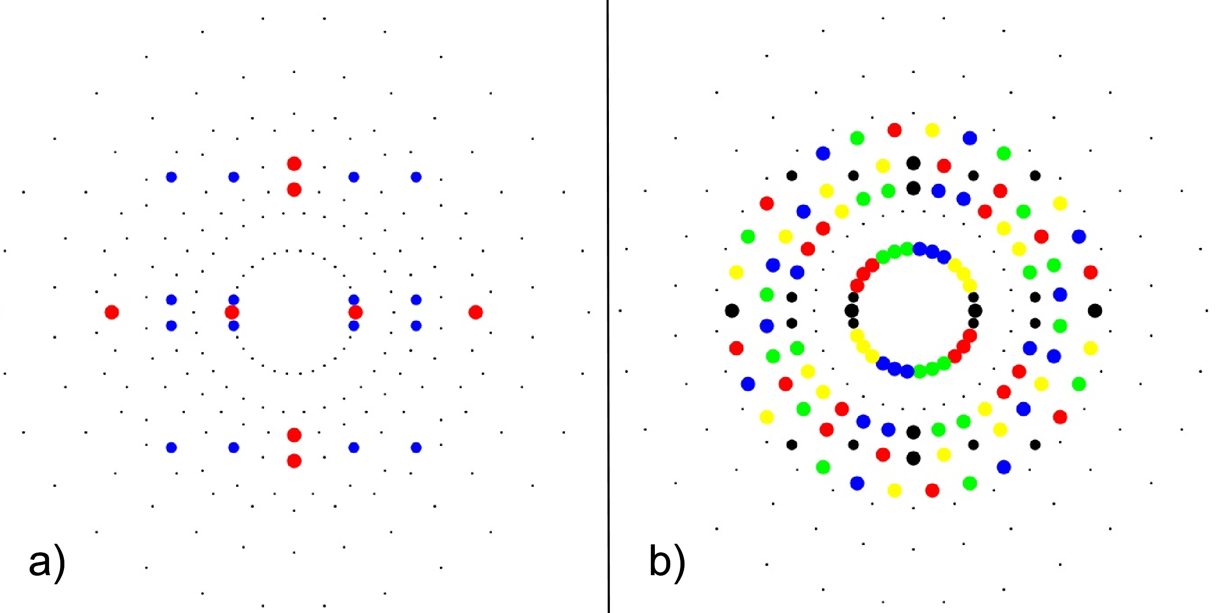
FIG. 3: a) 24-cell highlighting the 16-cell (red on-axis vertices) and 8-cell (blue off-axis vertices), b) Snub 24-cell highlighting four pi/5 rotations of the 24-cell (black) in red, green, blue, yellow.
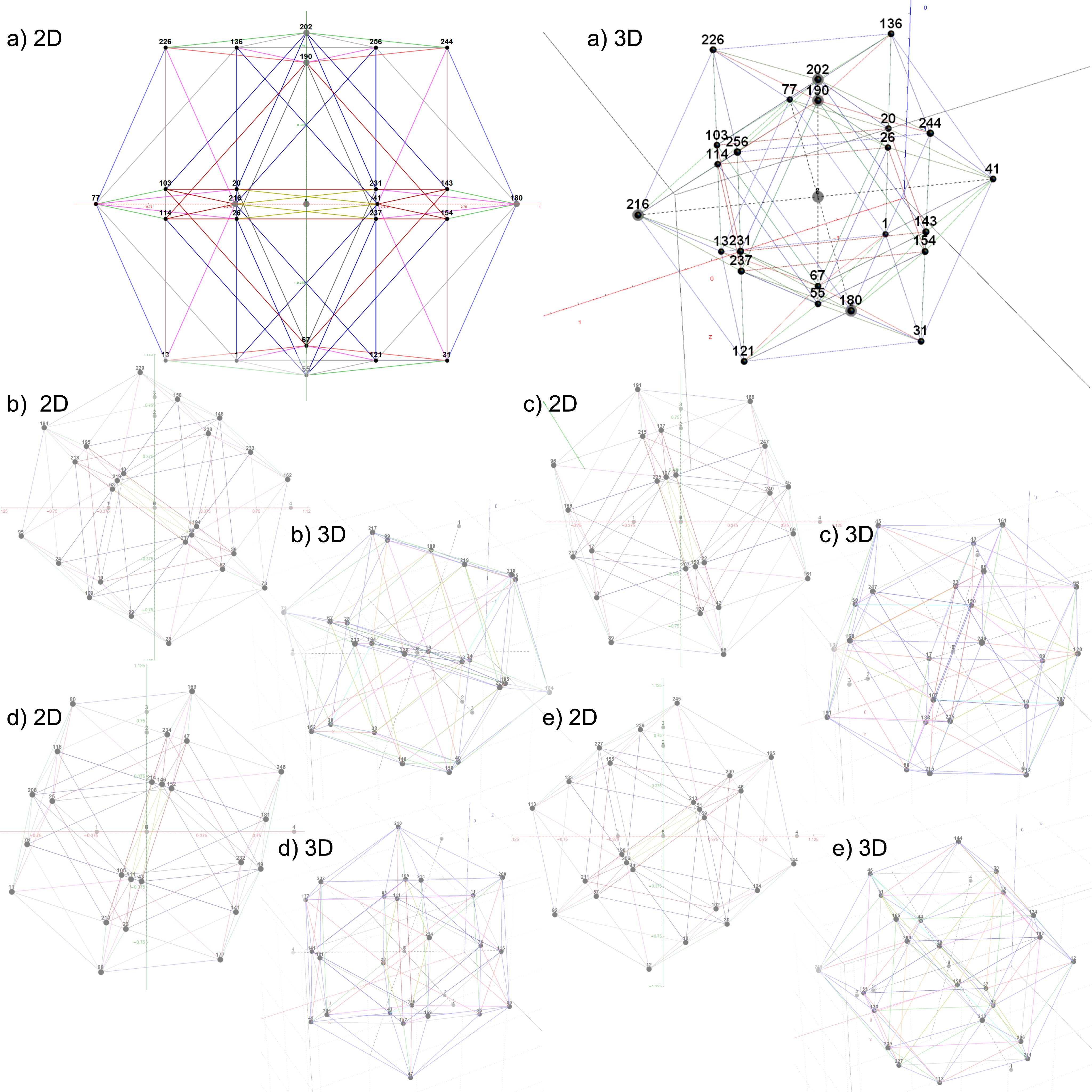
FIG. 4: The 5 24-cell decomposition of one 600-cell, each with 2D and 3D vertex numbered projections including edges; a)
24-cell, b-e) Snub 24-cells from four pi/5 rotations of the 24-cell in a)
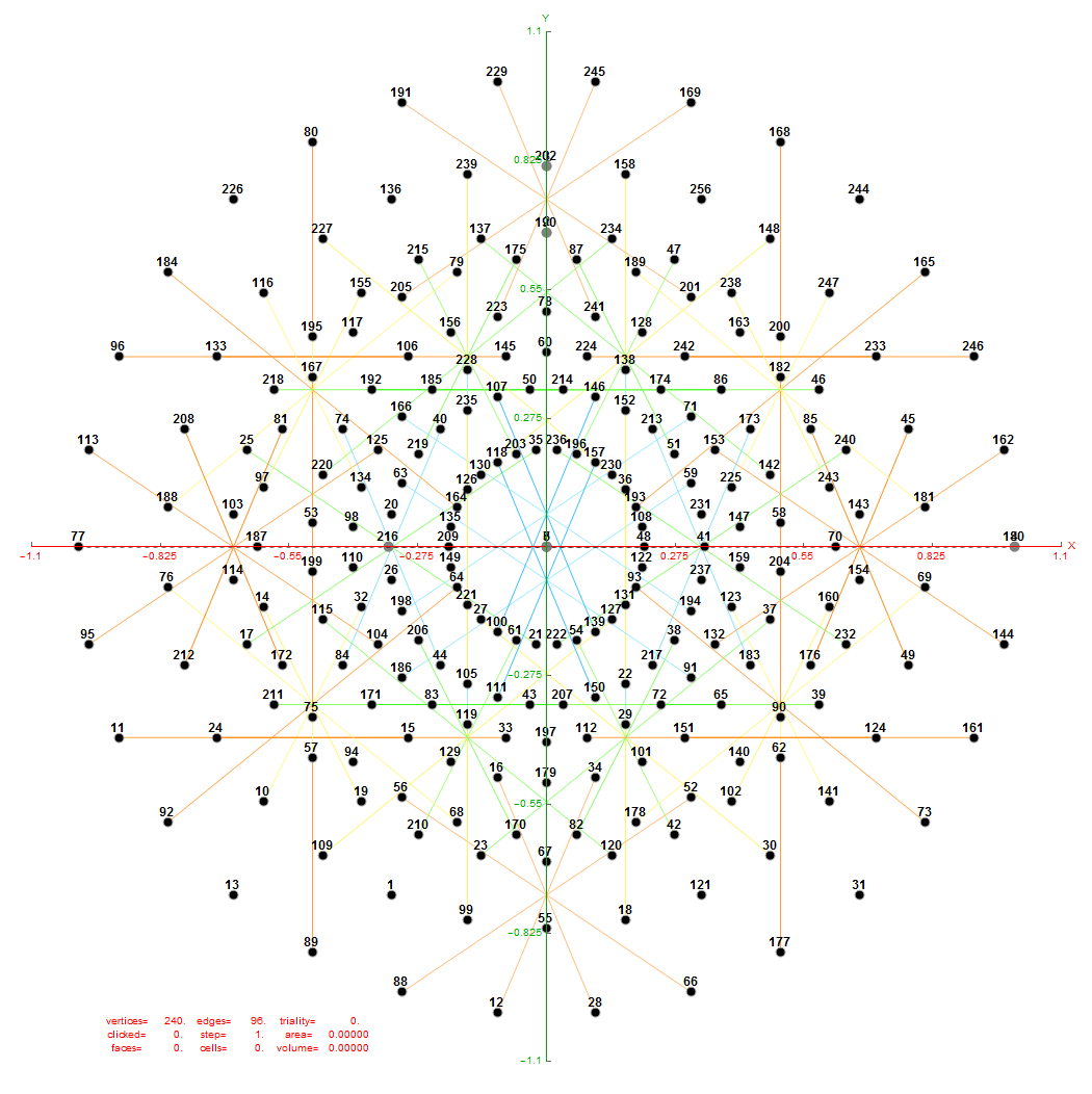
FIG. 6: Vertex numbered Petrie projection of the rotated E8, showing the 96 edges of 8D norm l = 2Φ which links the Snub 24-cell H4 and H4Φ (L<->R) vertices (Note: the 8 excluded positive E8 8-Orthoplex (or equivalently, the H4 and H4Φ 4-Orthoplex) “generator vertices” are shown as larger gray labeled axis dots which overlap their darker black E8 vertices)
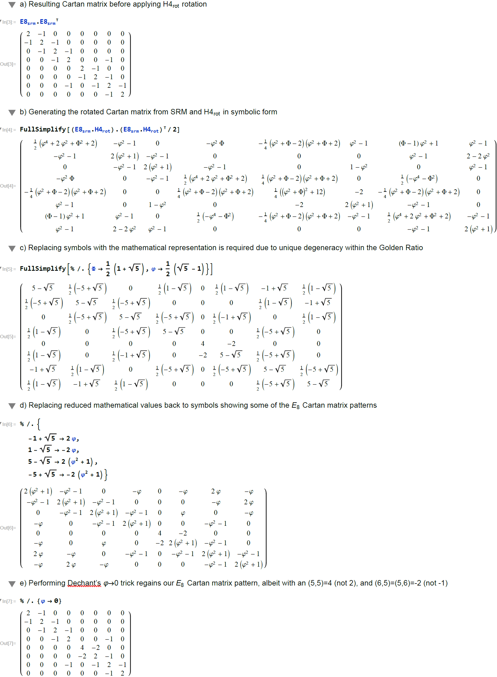
FIG. 7: Symbolic analysis using MathematicaTM comparing the Cartan matrix before and after rotating the simple roots matrix (E8srm) used to create it (Note: the resulting Cartan matrix is not precisely that of E8, even after applying the Dechant’s Φ=0 trick)
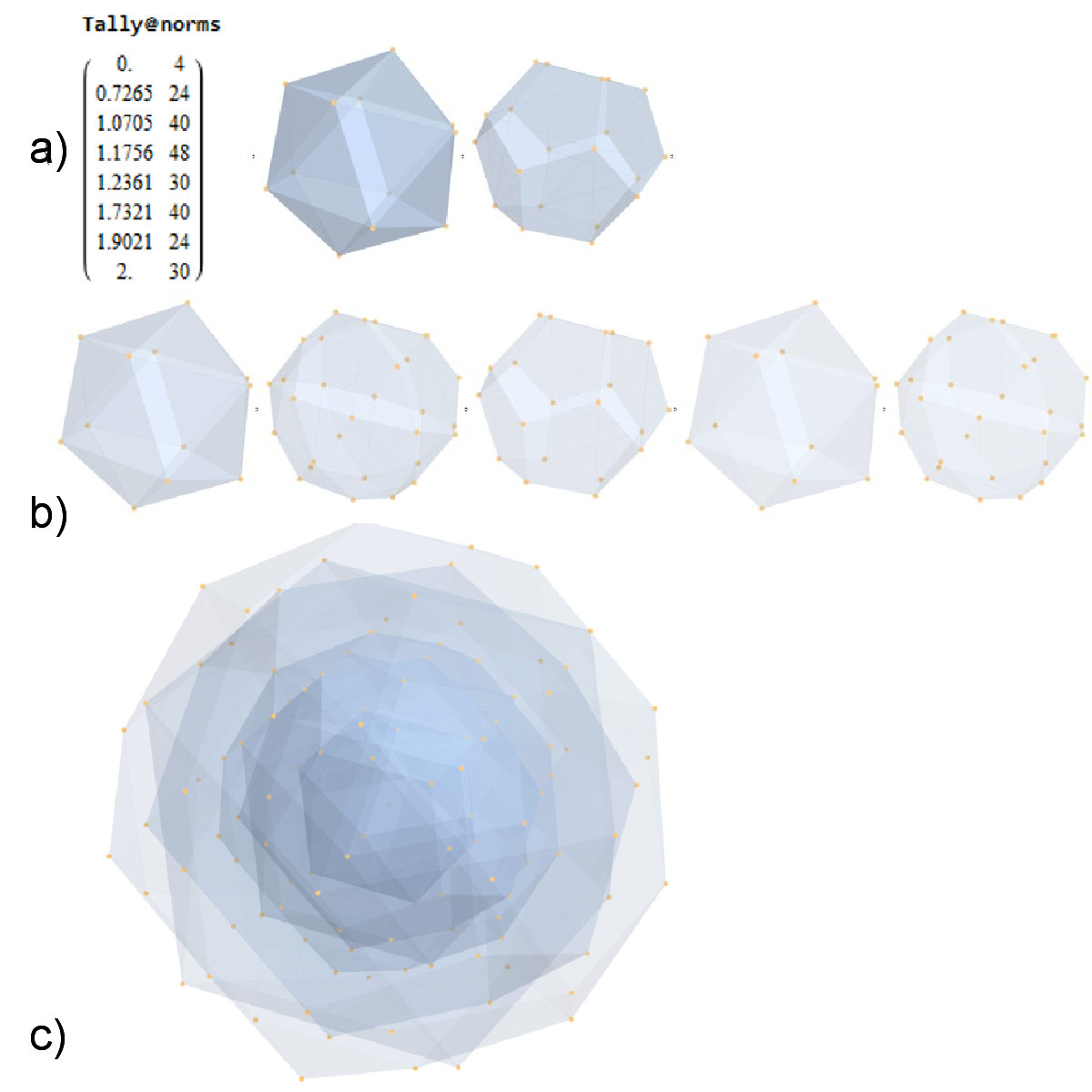
FIG. 8: a) Sorted list of the vertex norms with their grouped vertex counts. b) 3D surface models for each of the 7 hulls of vertices c) Combined 3D surface model with increasing transparency for each successive hull.
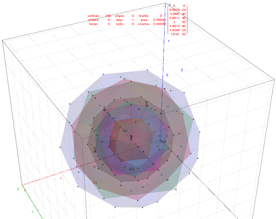
FIG. 11: 3D projection using an orthonormal basis on H4 and H4Φ vertices (i.e. the rotated E8)
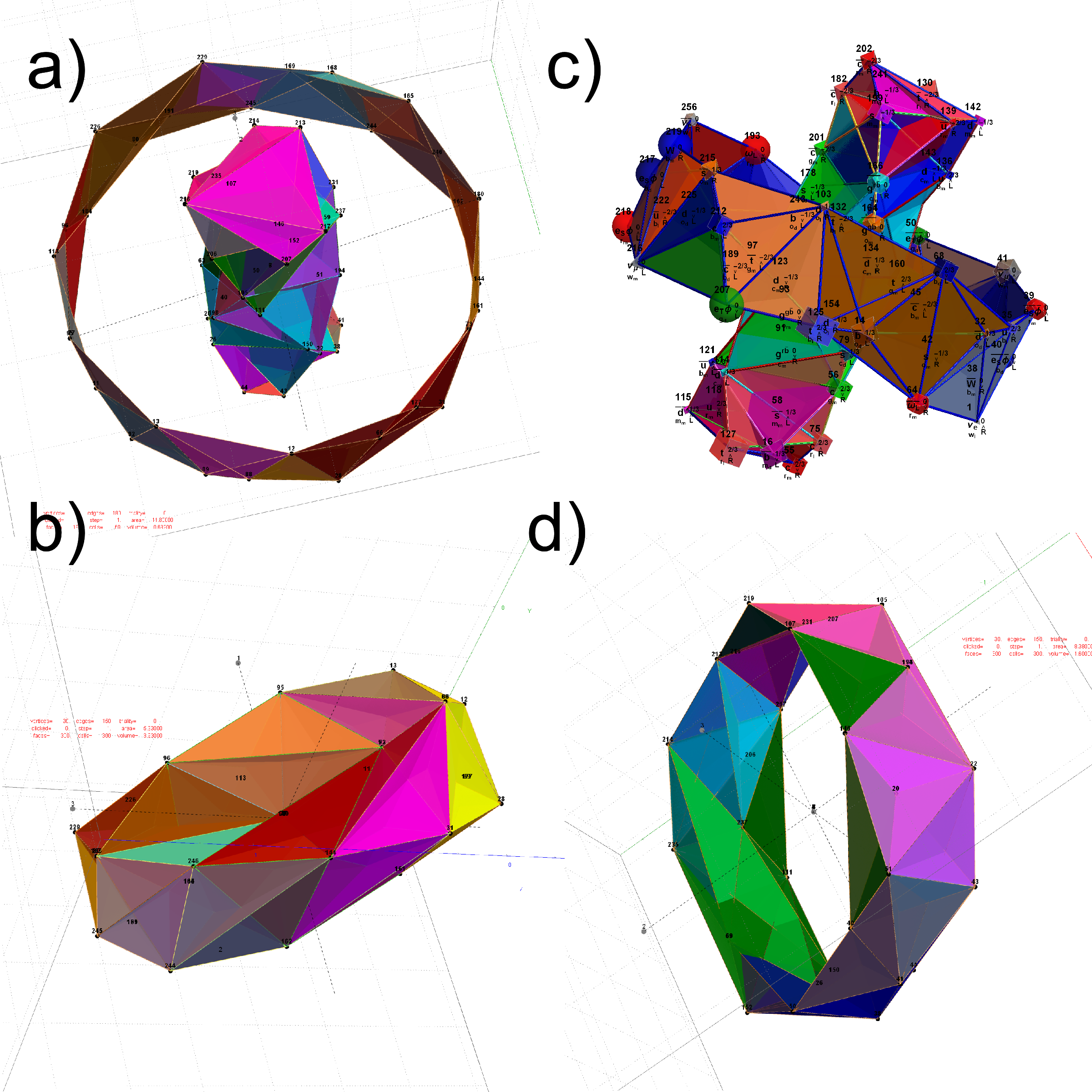
FIG. 12: The Beordijk-Coxeter Tetrahelix emerging from the 8 concentric rings of 30 E8 and H4+H4Φ Petrie projection vertices; a) H4 inner and outer ring in 3D, b) with vertex size, shape, color assigned from physics model, c-d) inner and outer ring in orthonormal projection of H4Φ
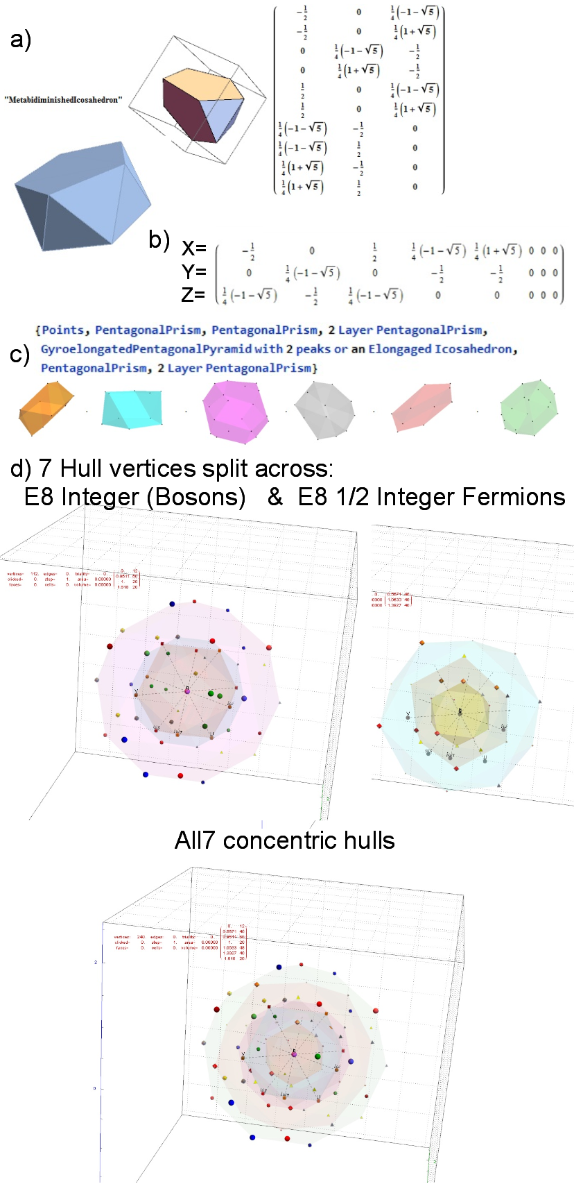
FIG. 15: MetabidiminishedIcosahedron (with its negated vertices gives the GyroelongatedPentagonalPyramid) Crystal Projection Prism projecting E8 a) the crystal prism geometry and vertices, b) the selected basis vectors, c) the individual 3D projected concentric hull objects, d) the combined set of concentric objects with progressively increasing transparency and tally of vertex norms.
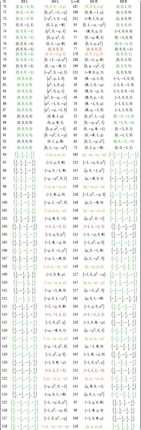
APPENDIX A: LIST OF E8 AND ITS ROTATED H4 AND H4Φ VERTICES
This table splits the E8 and its rotated H4 vertices into L/R 4D elements.
1. Table structure
The first column is an SRE E8 vertex index number derived from sorting the E8 vertices by their position based on the 256=2^8 binary pattern from the 9th row of the Pascal triangle (1, 8, 28, 56, 70, 56, 28, 8, 1) and its associated Cl8 Clifford Algebra. This construction is described in more detail in [3]. The odd groups (1,3,5,7,9) with (1,26,70,26,1) elements (respectively) are the 128 1/2 integer vertices. The even groups (2,4,6,8) with (8,56,56,8) elements (respectively) are the 112 integer vertices along with the 16 excluded 8 generator (and 8 anti-generator) vertices (2-9 and 248-255) with permutations of (1; 0; 0; 0; 0; 0; 0; 0) (a.k.a. the 8-Orthoplex), such that they indicate the basis vectors used for projecting the polytope.
Only the first half of the 240 vertices is shown, since the last half is simply the reverse order negation of the vertices
in the first half (e.g. the E8 vertex n=10 has as its’ negation 257-n=247). The middle column labeled L<->R indicates the vertex reference number that contains the same L as the R (and equivalently, the same R as the L, interestingly enough).
2. Table color coding
The E8 L/R columns’ green color-coded elements indicate that the 4D vertex rotates into the smaller H4 600-cell.
Conversely, the E8 L/R columns’ black color-coded elements indicate the 4D vertex rotates into the larger H4Φ
600-cell.
The H4 L/R columns’ red color-coded rows are 24-cell elements that always self-reference and are always members of the scaled up 600-cell H4Φ. The H4 L/R columns’ orange color-coded rows are 24-cell elements that always reference the negated elements in the range of 129-256 and are always members of the smaller 600-cell H4.